Hello dear Nerves users,
I’m trying to get a PWM output to show up on the 40-pin header on the MangoPI, specifically physical pin 35, or GPIO 38 as seen from Elixir. My goal is to have a few PWM channels physically available on the header to control them with the sysfs (/sys/class/pwm) interface.
To summarize :
- I think I found the relevant information in the D1 manual.
- I’m pretty sure I do not know how to properly apply it.
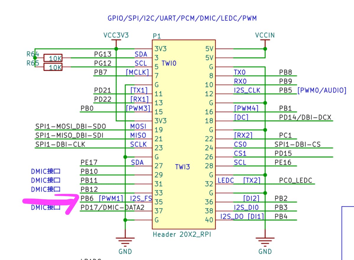
I found the following pin multiplexing table in the official D1 documentation (beware : 1300+ pages)

Further, since this pin should be handled by PB6, I found the relevant register address :

And the bit pattern to configure PB6 to use the PWM1 channel :

My understanding is that I should be able to get the PWM1 channel on PB6 / GPIO38 by setting the register at address 0x02000000 + 0x0030 to the bit pattern 000001010000000000000000 or 0x050000 (since PB6_SELECT is set by using the bits 27 to 24).
I found samples of DTS files online for similar purposes that I tried to modify, some compiling, and some not, but none having any tangible effect towards my goal.
I would greatly appreciate any direction on that matter. Am I looking at the wrong level of abstraction by thinking in terms of bit patterns and registers, and pinmux configuration is instead done at a slightly higher level ?
Best,
Lucas